Table of Contents
PiNAS v2 – Design Progress (HDD Cage & Caddies Validated)
Author(s): Louis Ouellet
PiNAS is back — and this time, it’s more than just an iteration.
Over the past few weeks, I’ve been deep into redesigning my Raspberry Pi-based NAS from the ground up. What started as a simple idea quickly turned into a series of design challenges, print tests, and unexpected lessons.
This article isn’t just about what works — it’s about what didn’t, what changed, and why.
What is PiNAS?
PiNAS is a compact Network Attached Storage (NAS) built around a Raspberry Pi and the RADXA Penta SATA HAT.
At its core, the idea is simple: create a NAS that anyone with a 3D printer can build, modify, and adapt. But in practice, that means balancing constraints like print volume, airflow, structural strength, and ease of assembly.
The goal isn’t just to build a NAS — it’s to design a platform that evolves.
Why a Redesign?
The first version of PiNAS relied on a pre-built hot-swap cage (Rosewill), which introduced several limitations:
- Increased cost of the build
- Limited flexibility in design
- Less control over airflow and structure
With PiNAS v2, the objective is to:
- Fully replace off-the-shelf components with custom-designed parts
- Improve aesthetics and overall finish
- Simplify assembly (less soldering, fewer external parts)
- Make the design adaptable to a wider range of use cases
What’s New in v2
Pretty much everything.
Rather than listing features again, it’s easier to say this: every decision in v2 is driven by lessons learned from v1 — especially around cost, complexity, and usability.
The biggest shift is moving from adapting existing parts to fully owning the design.
Design Goals
Instead of chasing features, the design goals for PiNAS v2 revolve around a few key principles:
- Keep it practical — something that can realistically be built at home
- Keep it flexible — adapt to different use cases and configurations
- Keep it reliable — especially when it comes to cooling and structural integrity
- Keep it simple — reduce unnecessary complexity during assembly
Everything else comes from these constraints.
HDD Cage Iterations


The HDD cage went through multiple iterations to refine tolerances and usability.
I tested the following tolerances:
- 0.0 mm
- 0.2 mm
- 0.4 mm
- 0.5 mm
- 0.6 mm
The best result was 0.5 mm tolerance.
Initial insertion was slightly tight, but after a few insertion/removal cycles, the caddies slid smoothly without any unwanted movement (no vertical or lateral play).
Additional improvements during iterations:
- Integration of a 22-pin SATA extender mount at the back for easier drive swapping
- Addition of airflow channels to improve cooling (identified during early prints)
- Increased wall thickness to support self-tapping screws
Overall, the cage proved to be structurally solid with no major weaknesses observed.
HDD Caddy Validation


The HDD caddy also required several iterations, especially around mounting and durability.
Tolerance testing for HDD fit:
- 0.0 mm
- 0.2 mm
- 1.0 mm
The best result was 0.2 mm tolerance, providing a secure fit without excessive force.
Key changes and findings:
- Threaded inserts were unreliable — heat caused slight deformation in PLA, leading to misalignment
- Switched to self-tapping screws, which:
- Improved consistency
- Reduced cost
- Simplified assembly
- Increased handle thickness from 4 mm to 6 mm
- Prevented bending and breaking when pulling the caddy out
These changes significantly improved both durability and usability.
Combined Fit Test


Initial combined tests show a clean and precise fit between the caddy and the cage.
The insertion feels controlled and stable, confirming that the tolerance pairing (0.5 mm cage / 0.2 mm caddy) works well together.
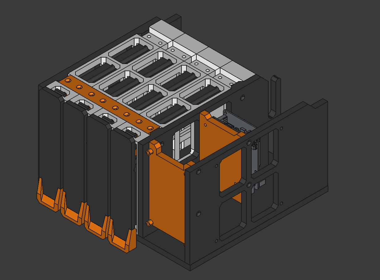
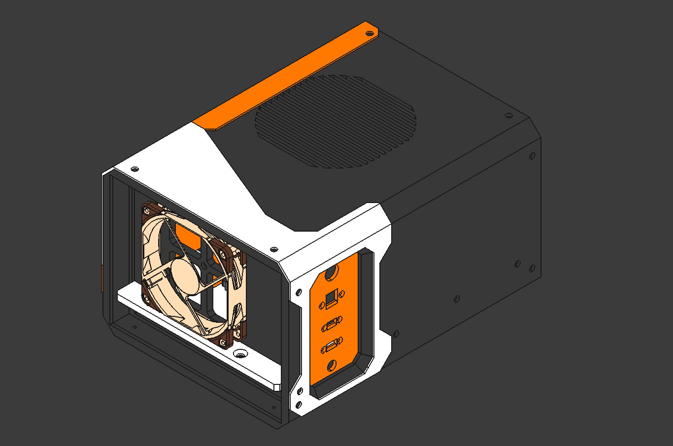
Internal Structure & Mounting
Work has started on the internal mounting system — and this is where things start getting a bit more interesting.
At this stage, it’s less about individual parts and more about how everything comes together: clearances, cable routing, and making sure assembly feels natural instead of frustrating.
This is usually where small design decisions have a big impact.
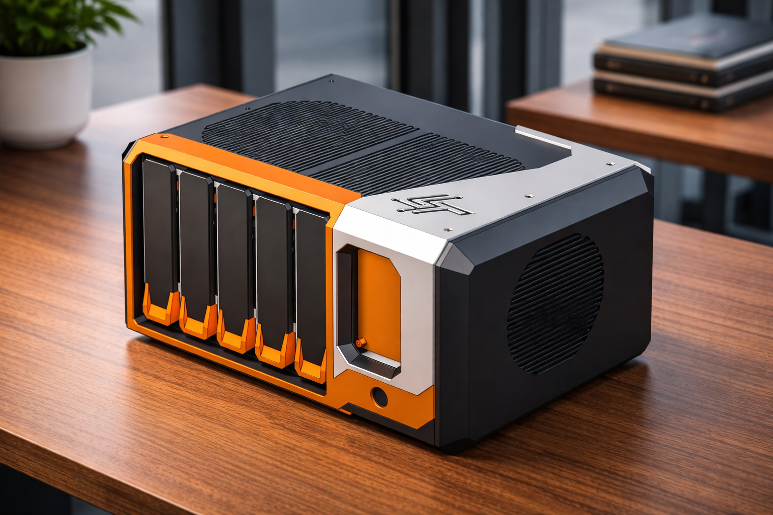
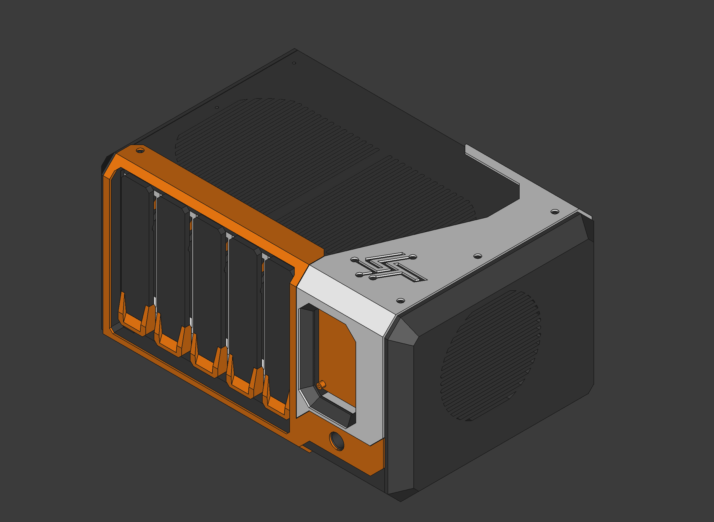
Outer Case Design
The outer casing is where the project really starts to take shape visually.
The goal here isn’t just aesthetics — it’s about creating something that feels intentional and cohesive, while still respecting the constraints of 3D printing.
At the same time, the design remains modular, allowing different configurations depending on the use case.
Planned Touch Interface
A 4.3“ touchscreen interface is planned, featuring a simple swipe-based UI with three main screens:
Screen 1 – System Overview
- Hostname
- IPv4 / IPv6
- CPU usage & temperature (circular graph)
- RAM usage
- RAID / ZPOOL health
- Storage usage
Screen 2 – Storage
- List of disks
- Serial numbers
- Slot/port mapping
- SMART status
- Disk temperature
Screen 3 – Network
- Interfaces (WiFi, Ethernet, USB)
- IP addresses
- Link speed
- Network usage
Current Status
- ✅ HDD Cage validated
- ✅ HDD Caddies validated
- 🔄 Full multi-bay assembly (next step)
- 🔄 Internal mounting plates
- 🔄 OLED/touchscreen integration
- 🔄 Cable validation
What’s Next
The next phase is all about bringing everything together.
That means validating a full multi-bay assembly, refining the internal structure, and starting work on the touchscreen interface.
Once the hardware is stable, the focus will shift toward the user experience — and eventually, a complete assembled system.
Closing Thoughts
PiNAS v2 is already a big step forward compared to the first version — not because of features, but because of how the design has matured.
There’s still a lot to build and validate, but the foundation is now solid.
The next update will focus on integrating the screen and software, followed by a full assembly.
And that’s where things should get really interesting.